It is recommended for you to read H100 Control Panel PDF provided by Generac.
H-Panel Accepts 12-24v input
CPU programming without official software
CPU has 10 pin JTAG connector near it
Google PowerPC to 10 pin JTAG to find the adapter.
Otherwise use 10 pin JTAG to adapter like PEMicro
Uses Motorola NXP based software with .run or similar S-Record configurations.
Use software like CodeWarrior to dump config or custom Linux applications as an alternative.
Resetting Faults
General Faults: Unplug the blue connector from the back of the ECM.
Continuous Circuit Test Faults: Unplug or jump the sensor associated with the fault.
Alarm Hold Off Delay
Some faults may be programmed to throw an alarm after they exceed a certain time.
Wr- Warning
HUIO (H Model Panel Universal Input Output): Refers to the module(s) inside the control panel that expand the IO for the H100, like the overfill sensors.
Wr Engine Stall
If this is immediately killing the engine, increase start detection rpm.
Relays
Engine Relays are the 4 relays behind H100 ECM
Relays 3/4 is Run/Start
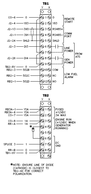
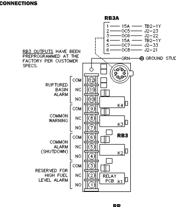
Alarm relays are at customer connections box
All connect to H100 through RS485
Outputs!
You can manipulate ECM outputs from Generac H100 in diagnostic menu, by changing 0 to 1.
H100 making engine run too fast but run smoothly
Make sure crank sensor spacing is correct
Reprogram parameters in GenLink.
Crank Sensor
Make sure crank sensors are spaced correctly when installed.
Waveform from crank sensor can be analyzed with oscilliscope
Output voltage from sensor is AC!
OHM range for 0D2244M is XXX.
Make sure tip of crank sensor isn’t broken off.
If you have two crank sensors… (advice pending).
Crank sensor voltage while cranking should be __ and running at 1800RPM should be ___.
How to Trace an Intermittent Issue
Navigate to the top right menu and change the left window to display alarm history for tracing intermittent problems.
Name of H100 Connector: 776164-5 (J1) and 776164-1 (J2); Pins 770854-1.
OBD/J1708/J1939/Deutsch DT support
OBD Support for P1034 oxygen sensor code and possibly dpf codes. (EPA Requirement)
J1939 to connect to ECM’s like Deere, Volvo, FPT NEF, FPT Cursor, Perkins.
Deutsch DT adapter has 120 ohm termination resistor.
J1939 Pinout
A: GND
B: 12V
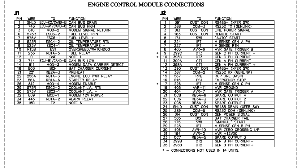
C: CAN L 743
D: CAN H 744
E: Can Shield
F: N/A (CAN2)
G: N/A (CAN2)
H: (N/A)
J: (N/A)
PID Proportional-Integral-Derivative Constants
KP (Proportional term) Affects how responsive actuator is
KI (Integral term) Accumulates past errors and applies a correction
KD (Derivative term) Tries to prevent actuator from going to far if it predicts it is going too fast
If the generator exceeds hz or rpm limit, the watchdog will shut the engine down.
The watchdog will potentially shut the engine down too if throttle actuator doesn’t adequately respond to commands.